ADC to PWM: The World Beyond ON/OFF
After playing around with DigitalIO, Timer Counter, Interrupt, I2C, and SPI, I thought it was time to work on Analog Digital Conversion.
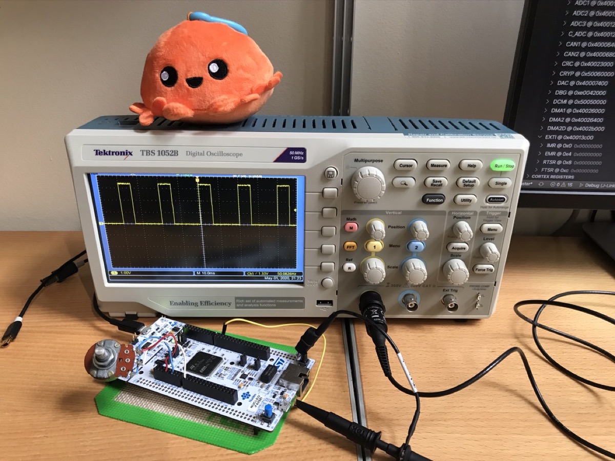
To experiment with embedded Rust ADC, I did a quick project that adjusted PWM duty cycle based on ADC values. There were no fancy analog sensors in my toy box. I used a potentiometer and monitored PWM outputs on my oscilloscope.
Although it was such a simple project, I found it really satisfying to see pulses respond to my turning the potentiometer. It was quite a different experience from toggling an LED. As my sensei Tom Igoe says, knowing whether a cat is on or off a mat is not always enough. Sometimes, we want to know how fat the cat is.
While a digital input to a microcontroller can tell you about discrete changes in the physical world, such as whether the cat is on the mat, or the cat is off the mat, there are times when this is not enough. Sometimes you want to know how fat the cat on the mat is. - Tom Igoe
Ingredients
Hardware
- Nucleo-F429ZI
- Potentiometer
Crates
stm32f4xx-halA Rust embedded-hal HAL for all MCUs in the STM32 F4 family
Code
Implementation
ADC
In order to use ADC on STM32 devices, we need to do the followings:
- Enable the ADC clock
- Enable the GPIO clock
- Configure the GPIO pin as an analog input
- Configure the ADC (clock, resolution, data alignment, etc.)
It sounded like a lot of work. But it turned out that ADC was as easy as ABC thanks to stm32f4xx-hal. After importing all the required modules, below was all I needed to enable and configure ADC.
let mut adc = Adc::adc1(dp.ADC1, true, AdcConfig::default());
I was curious to know what AdcConfig’s Default was. I looked up the doc and found this.
impl Default for AdcConfig {
    fn default() -> Self {
        Self {
            clock: Clock::Pclk2_div_2,
            resolution: Resolution::Twelve,
            align: Align::Right,
            scan: Scan::Disabled,
            external_trigger: (TriggerMode::Disabled, ExternalTrigger::Tim_1_cc_1),
            continuous: Continuous::Single,
            dma: Dma::Disabled,
            end_of_conversion_interrupt: Eoc::Disabled,
            default_sample_time: SampleTime::Cycles_480,
        }
    }
}
You can, of course, customize AdcConfig. But for this simple experiment, I only wanted to do one-shot conversion. No scanning, no external triggers, no DMA… I didn’t change anything.
After enabling ADC, I configured an analog input pin, PA3.
let gpioa = dp.GPIOA.split();
let pa3 = gpioa.pa3.into_analog();
I passed my pin pa3 to read() method to read a value on the pin.
let sample = adc.read(&mut pa3).unwrap();
iprintln!(itm(), "PA3: {}", sample);
Nucleo-F429ZI has 12 bit ADCs. So, a returned value from read() can be 0 ~ 4095. If you want to convert that to voltage, stm32f4xx-hal has a convenient method for that. Just pass the read value to fn sample_to_millivolts(&self, sample: u16) -> u16.
let millivolts = adc.sample_to_millivolts(sample);
iprintln!(itm(), "PA3: {}mV", millivolts);
PWM
I have to say I got lucky. A couple of days ago, the stm32f4xx-hal team released a new version, v0.8.0, and added PWM support. Without this update, it would have been difficult for me to do PWM.
I haven’t taken a close look at the PWM API yet. But it seems like we just need to pass a Timer, a pin (or pins), clocks, and desired frequency to create a PWM instance.
I initialized my PWM instance with PA8 pin and enabled it like this:
let pa8 = gpioa.pa8.into_alternate_af1();
let mut pwm = pwm::tim1(dp.TIM1, pa8, clocks, 50.hz());
pwm.enable();
My understanding is that the PWM period is determined based on clock configuration. get_max_duty() returns the maximum value you can pass to set_duty() method.
let max_duty = pwm.get_max_duty();
pwm.set_duty(max_duty); // 100% duty cycle
pwm.set_duty(0); // 0% duty cycle
ADC -> PWM
After configuring ADC and PWM, I repeated the followings in the infinite loop.
- Read an ADC value
- Scale the 12 bit ADC value to the range of
0tomax_duty - Set PWM duty
loop {
    let sample = match adc.read(&mut pa3) {
        Ok(x) => x,
        Err(_) => continue,
    };
    let scale = sample as f32 / 0x0FFF as f32;
    pwm.set_duty((scale * max_duty as f32) as u16);
}
That was it. Simple ADC and PWM with stm32f4xx-hal. I will explore other ADC features in future projects.