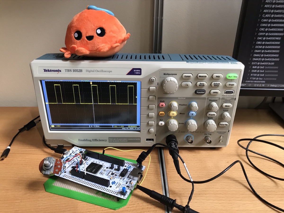
Interrupt Based ADC
Polling in a loop is the simplest way to use the ADC. But it makes it difficult to run other codes while the ADC is running. It would be nice if we can make it interrupt-based. This post will show how to do a simple interrupt based ADC in embedded Rust.
Ingredients

Hardware
- Nucleo-F429ZI
- Potentiometer
Crates
stm32f4xx-halA Rust embedded-hal HAL for all MCUs in the STM32 F4 family
Code
EOC Interrupt
Each time ADC completes a conversion, the EOC (End of Conversion) flag is set and the ADC_DR register (the register that holds ADC value) can be read. For this week’s little experiment, we use the EOC flag for interrupts. Just like last week’s ADC project, our output will be PWM. This time, we will adjust the PWM duty cycle in the ISR context instead of the user context.
In stm32f4xx-hal’s adc.rs, the EOC interrupt is disabled by default. We explicitly enable the interrupt using AdcConfig like this.
let config = AdcConfig::default()
    .end_of_conversion_interrupt(Eoc::Conversion);

let mut adc = Adc::adc1(dp.ADC1, true, config);
Next, we configure an analog pin and ADC channels. We use only one channel for this example project.
let pa3 = gpioa.pa3.into_analog();
adc.configure_channel(&pa3, Sequence::One, SampleTime::Cycles_112);
We are ready to go. Let’s start ADC. The method below does the following:
- Enable ADC
- Clear the EOC flag
- Set SWSTART bit (which triggers conversion)
- Wait until conversion starts.
adc.start_conversion();
Since we want to access ADC module in the interrupt handler, we move adc to Mutex.
free(|cs| {
    ADC.borrow(cs).replace(Some(adc));
});
Don’t forget to enable the ADC interrupt in the NVIC (Nested Vector Interrupt Controller).
unsafe {
    stm32::NVIC::unmask(stm32::interrupt::ADC);
}
Interrupt Handler
The ADC interrupt is now enabled. Whenever the EOC flag is set, it generates an interrupt request and calls up this interrupt handler.
#[interrupt]
fn ADC() {
    free(|cs| {
        if let (Some(ref mut adc), Some(ref mut pwm)) = (
            ADC.borrow(cs).borrow_mut().deref_mut(),
            PWM.borrow(cs).borrow_mut().deref_mut(),
        ) {
            // Reading the result from the ADC_DR clears the EOC flag automatically.
            let sample = adc.current_sample();
            let scale = sample as f32 / 0x0FFF as f32;
            pwm.set_duty((scale * pwm.get_max_duty() as f32) as u16);
            // restart ADC conversion
            adc.start_conversion();
        }
    });
}
In the handler, we take the ADC module out of Mutex and call current_sample(). This method reads from the ADC_DR register and clears the EOC flag. We update the PWM duty cycle based on the ADC value, and finally, restart the conversion by calling start_conversion() before we move out of the ISR.
That’s it! Now our main looks like the code below. There is nothing in the loop. ADC reading and PWM adjustment are all happening in the ISR.
#[entry]
fn main() -> ! {
    let dp = stm32::Peripherals::take().unwrap();
    let rcc = dp.RCC.constrain();
    let clocks = rcc.cfgr.freeze();
    let gpioa = dp.GPIOA.split();

    // Configure PWM
    let pa8 = gpioa.pa8.into_alternate_af1();
    let mut pwm = pwm::tim1(dp.TIM1, pa8, clocks, 50.hz());
    pwm.enable();

    // Configure ADC
    let config = AdcConfig::default().end_of_conversion_interrupt(Eoc::Conversion);
    let mut adc = Adc::adc1(dp.ADC1, true, config);
    let pa3 = gpioa.pa3.into_analog();
    adc.configure_channel(&pa3, Sequence::One, SampleTime::Cycles_112);
    adc.start_conversion();

    // Move shared resources to Mutex
    free(|cs| {
        ADC.borrow(cs).replace(Some(adc));
        PWM.borrow(cs).replace(Some(pwm));
    });

    // Enable interrupt
    unsafe {
        stm32::NVIC::unmask(stm32::interrupt::ADC);
    }

    loop {}
}