ADC: Injected Conversion Mode
Our embedded Rust experiments on STM32 platform continues. This week, we explore ADC’s injected conversion mode. The application note AN3116 explains what injected conversion mode is.
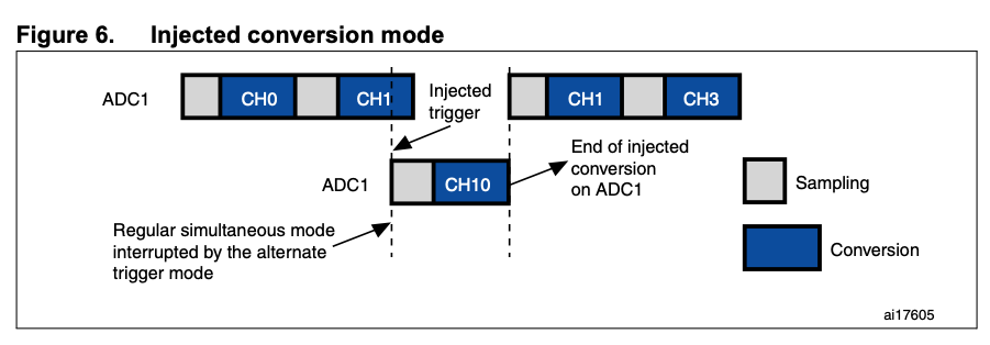
This mode is intended for use when conversion is triggered by an external event or by software. The injected group has priority over the regular channel group. It interrupts the conversion of the current channel in the regular channel group.
Injected conversions can be triggered by software or by hardware (timers or external pins). Injected conversions have higher priority and they can interrupt regular conversions immediately. A use case I can think of is that we run regular sequence conversion in a loop or something and interrupt that when needed.
Components
Hardware
- Nucleo-F429ZI
- Potentiometer
Crates
stm32f4xx-halA Rust embedded-hal HAL for all MCUs in the STM32 F4 family
Code
Implementation
This week’s experiment demonstrates injected conversion mode using a timer as an external trigger source. Here are the things this post covers:
- Configure Timer (the trigger source) in PWM mode
- Configure ADC
- Configure External Trigger source
- Set up an analog input pin
- Configure ADC channel with ADC peripheral and the analog pin
- Enable ADC interrupt
- Read ADC value in ISR
Configure PWM
One way to configure a timer in PWM mode is to use stm32f4xx-hal’s pwm module. pwm module routes a timer’s output to an output pin. Although output from a pin is not required to use a timer as an external trigger, being able to see the pulse may be helpful for debugging/troubleshooting.
In the code below, we create a pwm instance with TIM1 and set its frequency to 10Hz. This will generate 0.1 seconds pulse.
let pa8 = gpioa.pa8.into_alternate_af1();
let mut pwm = pwm::tim1(dp.TIM1, pa8, clocks, 10.hz());
let max_duty = pwm.get_max_duty();
pwm.set_duty(max_duty / 2);
pwm.enable();
If you don’t want to use stm32f4xx-hal’s pwm module, it is also possible to directly configure a timer in output mode. The code below shows how to select PWM mode 1, set duty, enable the channel, and enable the timer’s main output.
let _tim = Timer::tim1(dp.TIM1, 10.hz(), clocks);
configure_timer1();

// ----

fn configure_timer1() {
    unsafe {
        let tim = &(*TIM1::ptr());
        tim.ccmr1_output()
            .modify(|_, w| w.oc1pe().set_bit().oc1m().pwm_mode1());

        // Set the duty cycle
        tim.ccr1.modify(|_, w| w.ccr().bits(1));
        // Enable the channel
        tim.ccer.modify(|_, w| w.cc1e().set_bit());
        // Enable the TIM main Output
        tim.bdtr.modify(|_, w| w.moe().set_bit());
    }
}
Configure ADC
Next, we configure our ADC in a way it -
- starts a conversion when triggered by
TIM1 - generates an interrupt request upon the end of conversion
We use AdcConfig to do that. Here, we specify the rising edge of TIM1’s signal to be the external trigger source.
let config = AdcConfig::default()
    .end_of_conversion_interrupt(Eoc::Conversion)
    .external_trigger(TriggerMode::RisingEdge, ExternalTrigger::Tim_1_cc_1);

let mut adc = Adc::adc1(dp.ADC1, true, config);
We now set up an analog pin and configure ADC channel.
let gpioa = dp.GPIOA.split();
let pa3 = gpioa.pa3.into_analog();
adc.configure_channel(&pa3, Sequence::One, SampleTime::Cycles_112);
adc.enable();
Enable ADC Interrupt
Since we need to access our ADC instance in ISR contexts, we declare a Mutex and move our ADC instance to it after initialization.
static ADC: Mutex<RefCell<Option<Adc<stm32::ADC1>>>>
    = Mutex::new(RefCell::new(None));

// ----

// Move the shared resource to Mutex
free(|cs| {
    ADC.borrow(cs).replace(Some(adc));
});
Finally, enable ADC interrupt with the NVIC.
unsafe {
    stm32::NVIC::unmask(stm32::interrupt::ADC);
}
Interrupt Handler
That is it. Injected conversion should be triggered on the rising edge of the signal.
The rest is pretty much the same as last week’s ADC experiment. When a conversion is done, EOC end of conversion bit is set and an interrupt request is generated.
In the interrupt handler below, we read the currently available ADC value and print it out. current_sample() reads the result from ADC’s DR register and clears the EOC flag automatically. There is no need to call clear_end_of_conversion_flag().
#[interrupt]
fn ADC() {
    free(|cs| {
        if let Some(ref mut adc) = ADC.borrow(cs).borrow_mut().deref_mut() {
            let sample = adc.current_sample();
            iprintln!(itm(), "PA3: {}", sample);
        }
    });
}